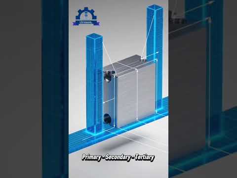
When it comes to modern engineering and component fabrication, precision is everything. Whether you are designing intricate mechanical parts or configuring heavy-duty industrial equipment, clear communication between design and production teams is critical. This is where Geometric Dimensioning and Tolerancing (GD&T) comes into play—specifically, the core concept of datums.
Datums serve as the foundational building blocks for technical drawings, ensuring that components created for high-precision manufacturing machinery meet exact specifications every single time.
What is a Datum in GD&T?
In GD&T, a datum is a theoretically exact point, axis, line, or plane that acts as a reference frame for measurements. Think of it as a fixed baseline or home position. When creating an engineering drawing, designers use datums to establish control points from which all geometric tolerances—such as parallelism, perpendicularity, flatness, and position—are measured.
While a theoretical datum is a mathematically perfect surface, physical components always have minor real-world variations. Therefore, machinists use a "datum feature" (an actual physical surface, hole, or edge on a part) to establish the datum reference frame during production and quality inspection.
Why Are Datums Crucial for Equipment Fabrication?
Without datums, interpreting an engineering drawing would involve guesswork, leading to assembly errors and costly material waste. Datums provide several key advantages:
- Consistency and Repeatability: Datums ensure every component maintains identical spatial orientation, guaranteeing that parts fit together seamlessly within complex manufacturing machinery.
- Streamlined Quality Control: Quality control inspectors rely on defined datums to align parts correctly on Coordinate Measuring Machines (CMMs) for accurate measurement verification.
- Cost Reduction: By removing ambiguity from engineering drawings, GD&T minimizes misinterpretation, significantly reducing rework, scrap rates, and assembly line downtime.
The Datum Reference Frame (3-2-1 Rule)
To fully lock a part's orientation in three-dimensional space, GD&T utilizes a Datum Reference Frame (DRF) consisting of three key references:
- Primary Datum: Contacts the part at a minimum of three points to immobilize three degrees of freedom (usually a primary flat surface).
- Secondary Datum: Contacts the part at a minimum of two points to immobilize two additional degrees of freedom (often a perpendicular edge).
- Tertiary Datum: Contacts at a single point to immobilize the final degree of freedom.
Mastering the fundamentals of datums allows engineers and machinists to collaborate seamlessly, ensuring optimal component alignment and reliable performance across modern manufacturing machinery.