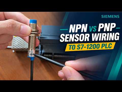
In modern factory automation, integration is everything. Whether you are building an automated assembly line or upgrading control panels, successfully connecting an industrial sensor to your Programmable Logic Controller (PLC) is a fundamental skill every technician and engineer must master.
Among the most popular choices for modern control systems is the Siemens S7-1200 PLC. However, beginners and experienced technicians alike often run into confusion when dealing with NPN (sinking) and PNP (sourcing) digital inputs. In this step-by-step guide, we will break down how to properly wire both types of 3-wire proximity sensors to your Siemens S7-1200 PLC.
Understanding NPN vs. PNP Logic
Before picking up your tools, it is crucial to understand how current flows in each switch type: - PNP (Sourcing): The sensor switches positive voltage (+24V DC) to the PLC input when triggered. - NPN (Sinking): The sensor switches ground (0V DC / M) to the PLC input when triggered.
The Siemens S7-1200 digital input channels are versatile because the common terminal (1M) determines whether the input card accepts sinking or sourcing inputs.
How to Wire a PNP Industrial Sensor
PNP proximity switches are the most common standard in European industrial automation. Because a PNP sensor outputs +24V DC, the PLC input bank common terminal must be connected to 0V DC (M) to complete the circuit.
- Power Supply: Connect the sensor's Brown wire to +24V DC and the Blue wire to 0V DC (M).
- Common Terminal Setup: Wire the 1M terminal on the Siemens S7-1200 to 0V DC (M).
- Signal Input: Connect the Black wire (signal output) from the PNP industrial sensor to your target digital input point (e.g., %I0.0).
How to Wire an NPN Industrial Sensor
NPN sensors pull the signal wire down to ground when active. To read an NPN switch, you must adjust the Siemens S7-1200 common terminal configuration so it provides +24V DC to the input channel.
- Power Supply: Connect the sensor's Brown wire to +24V DC and the Blue wire to 0V DC (M).
- Common Terminal Setup: Wire the 1M terminal on the Siemens S7-1200 to +24V DC.
- Signal Input: Connect the Black wire (signal output) from the NPN device directly to the PLC digital input channel (e.g., %I0.1).
Final Thoughts
Correctly wiring your industrial sensor ensures reliable signal detection, prevents unexpected equipment downtime, and protects your hardware modules from accidental short circuits. Always double-check your voltage polarity and common (1M) connections before turning on the power supply to your Siemens S7-1200 control panel.